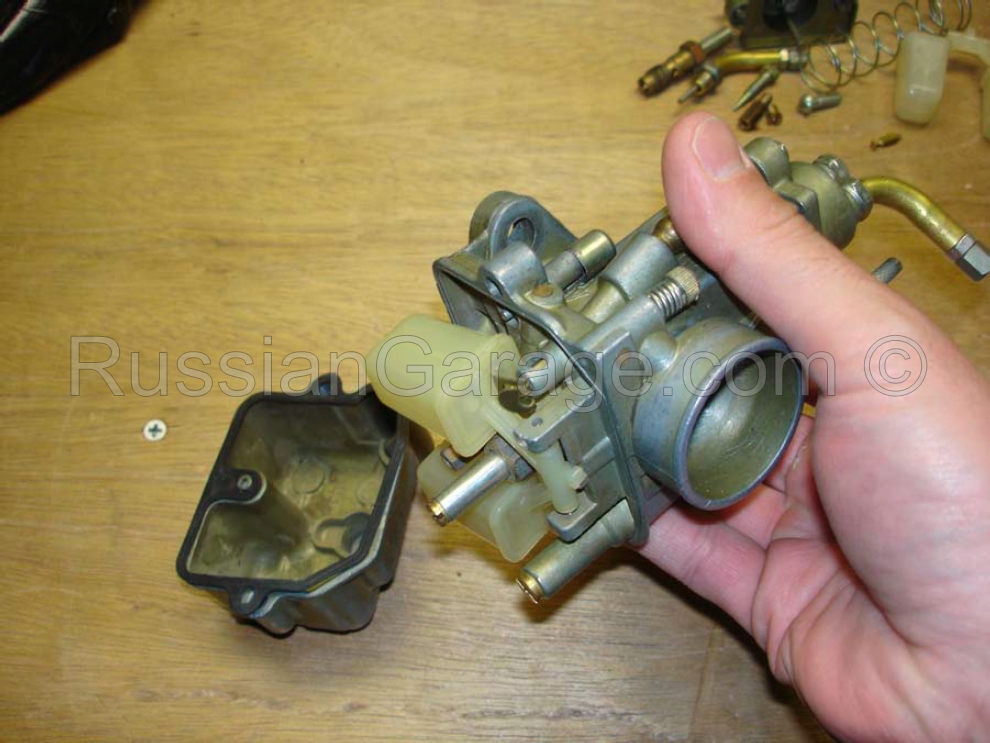
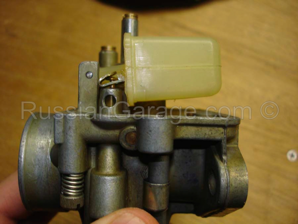
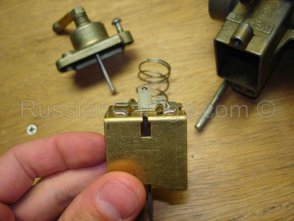
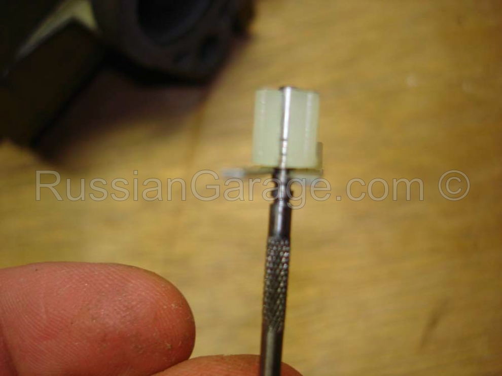
Adjustment and repair of the PEKAR K65T/63/62 carburetors
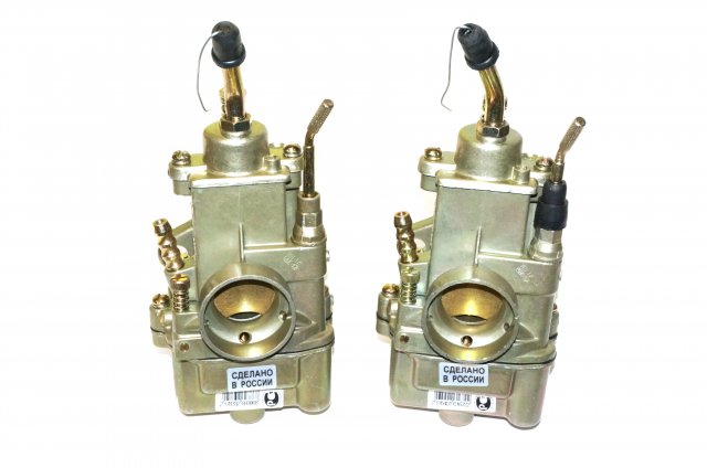
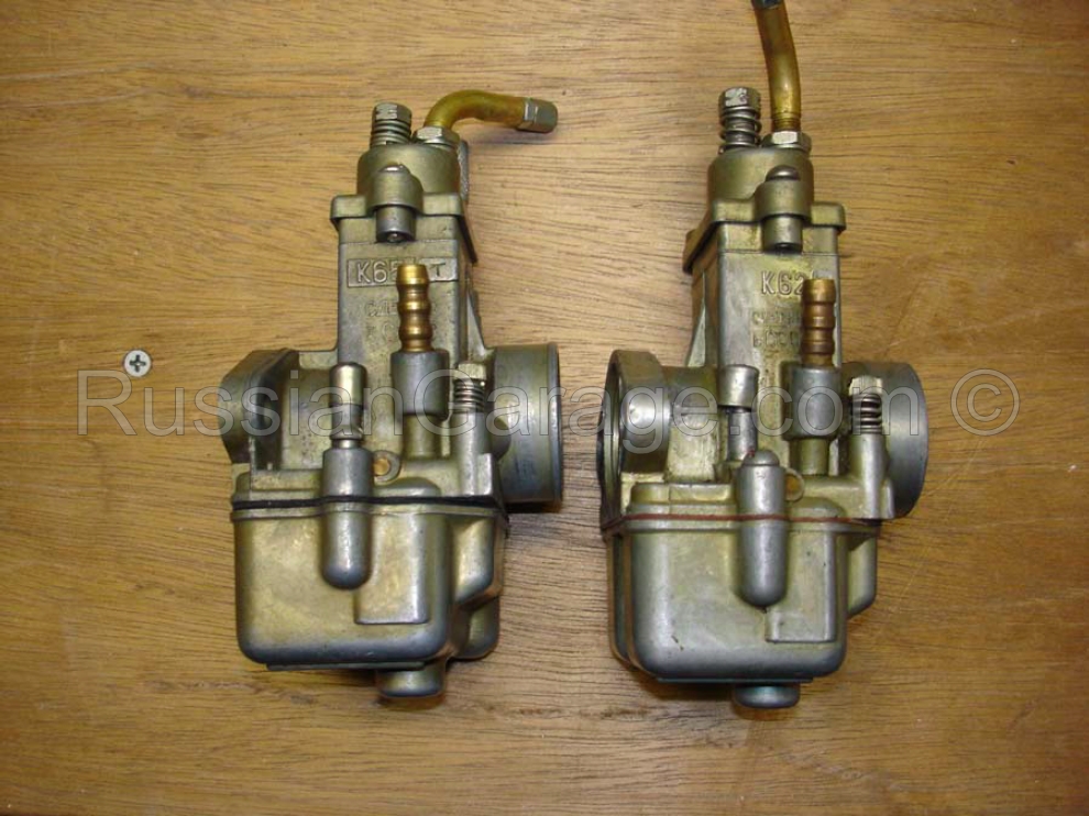
PEKAR K65T Left, Right carburetors
Introduction
This manual was designed for the Ural and Dnepr enthusiasts interested in getting to know their Pekar K65/63/62 carburetors. We will cover basic operation, tuning, and overhaul; all of which are relatively simple. Before disassembly, you should understand the basic concepts of carburetion, which, are as follows:
1. Air enters the carburetor throat through the air filter system.
2. Fuel from the tank, which is metered into the bowl by the float mechanism, is siphoned up through the jets (depending upon the amount of air entering), into the throttle body by the passing air and low pressure where it is atomized into an approximate mixture of 14.7:1 (weight). This air volume is changed by the height of the slides, drawing more or less fuel, directly controlled by the throttle. Since each unit has it’s own cable, it’s important that each slide operates somewhat the same as the other.
3. The air/fuel mixture passes into the body of the carburetor, past the intake seals, and into the combustion chamber.
Depending upon the operating range, this is mostly dependent upon the idle jet and idle mixture screw (idle), radius of the jet needle (1/8 to 1/4 throttle), tapered section of jet needle and main jet (1/4 to open throttle). These are sometimes called the Idle system, intermediate system, and high speed system. If the engine runs well at idle and all is tuned, but you get pinging or knocking under load, if it’s not a timing issue, it might be an overly lean mixture. Adjust the jet needle as necessary to compensate. It’s easy…
Now, when everything is cold, fuel doesn’t vaporize well, and this is where the enrichining, or choke system is used. With the K65, this is the knurled rod which twists up and rotates 90 degrees to lock. This unports another jet which allows an enrichened mixture into the chamber. This system is dependent upon springs and seals to properly operate.
How to operate in the cold weather? Open the fuel shutoff valve, depress the ticklers (float depressors) a few times, activate the choke, and it should start immediately. Simple. Really…a tuned Dnepr carburetor usually operates very well.
The next steps are to tune and possibly disassemble and overhaul the unit. This is relatively easy, requiring only a few tools and a clean work area (lots of little bits). Even better,
purchase a repair kit in our store here!!!
I. Adjustment of K65-K63 carburetors used on Dnepr and Ural motorcycles.
Prior to commencing carburetor adjustment, check the electrode gaps on the spark plugs, properly adjust timing, adjust breaker point gap, and adjust the valves.
If necessary, on new carburetors, remove the cover and disconnect the rev limiter (remove the metal rod) See the illustrations contained in this document.
1. Adjusting the slides of each unit and throttle free play.
This step sets the initial slide height of the units. By adjusting the top nut, you set the amount of air allowed through the chamber at idle. This is the initial static adjustment. Throttle slack is usually set to allow about 2 mm of play. This compensates for the turning of the handlebars. The slide adjustment (in conjunction with idle mixture) directly sets the idle speed.
a. There must be a height on the slides which allows for proper idle. Adjust this as necessary by loosening the locknut at the top of the unit (38) and adjusting the top nut as necessary to adjust the slide height. When adjusted, tighten locknut.
2. Intake inspection.
This is to prevent an overly lean condition downstream of the fuel/air metering. If you have a leak here and continue to adjust the carburetors, more than likely this will degrade over time, causing a lean mixture and subsequent damage.
a. Inspect the intake gasket of each unit for wear, replace if necessary. Tighten each nut, using care not to warp the flanges (they distort very easily). One method used here could be spring nuts.
Warm up engine.
b. To start engine, first depress (18) on the side of each unit for a few seconds. These “ticklers” manually actuates the floats allowing fuel into the bowl (12). If the conditions warrant you may depress the tickler until fuel flows from the drain hole, though this is rarely necessary. The choke levers are the vertical knurled rods. To lock them in place, pull up and rotate each 90 degrees. With the ignition off, kick through 1 to 3 times, which will draw fuel into the cylinders, effectively “priming” the engine.
3. Minimum idle speed.
a. Adjust minimum idle speed using (38) Be sure to adjust in small increments, alternating cylinders.
4. Adjust idle mixture.
a. Gradually turn screw (24) counterclockwise until engine begins to miss (leaning mixture), steadily turning screw clockwise until engine no longer misses. It is better to have a slightly rich mixture over a slightly lean mixture.
b. Again, adjust (38) for best idle if necessary. Repeat 4 and 5 on each cylinder.
5. Statically synchronize carburetors.
a. Remove the spark lead from one side. Note engine speed. Reconnect.
b. Remove the spark lead from the other side. Note engine speed. Adjust (38) as necessary to equalize sides.
6. Mixture check.
a. Verify proper operation by quickly opening and closing the throttle. If the engine sputters when the throttle is opened, the mixture is overly lean (24). Adjust (24) clockwise 1/4 to 1/2 turn, or until this no longer occurs. If the engine sputters when the throttle is closed, the mixture is too rich, adjust (24) counterclockwise.
7. Dynamically synchronize carburetors.
a. This is tricky, and not really recommended, but it is a way to balance the carburetors when there is no other way. The point is to adjust the slides using engine load as the indicator. This will ensure that when the throttle is opened, the slides have uniform travel.
1. Place the motorcycle on the center stand and start. Shift into the highest gear and increase the speed to about 40-50 kmH.
2. Fix the throttle in position.
3. Short one spark plug to the cylinder, using a nail or something similar.
4. Watch the speedometer and use this for reference.
5. Re-connect the plug wire.
6. Repeat on other side, noting the new indication of the speedometer, adjusting the slide (as in the beginning of this doc) as necessary to achieve the same speed as the other unit.
II. Detailed tuning of K65-K63 carburetors.
1. Adjusting mixture for operating under load conditions
This step is for tuning the mixture for mid to upper range operations of the K63-65. For 1/8 to 3/4 throttle position, the mixture is dependent upon the jet needle taper and the needle jet (main jet). Altitude and seasonal changes can warrant this step. If you hear “popping” when increasing the throttle, this usually indicates a lean condition.
a. Adjustment of the mixture is accomplished by moving needle (34) along the cleat (4) adjusting the locknut (3). Moving the needle up richens the mixture, moving the needle down leans the mixture under these ranges of operation. Each revolution of the needle raises it approximately .5 mm.
Notes:
1. These carburetors require the manufacturers air filter to be attached, without leaks, to function properly. At a minimum, make sure your intake system is freee of leaks when tuning the carburetors.
2. Do not change the manufacturers recommended intake setup unless necessary. Make all adjustments with the intake system attached.
3. Do not clean the carburetors with anything other than gasoline or carb cleaner (no solvents). Do not clean any of the metering devices with wire or needles.
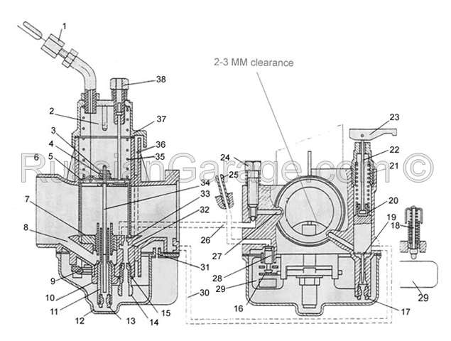
K63 (similar to K65)
1 – Locknut; 2 – throttle limiter; 3 – locknut; 4 – jet needle; 5 – throttle; 6 – body; 7 – nozzle chamber; 8 – atomizer air duct; 9 – float lever pin; 10 – atomizer body; 11 – atomizer; 12 – float chamber cover; 13 – main jet; 14 – idle jet; 15 – lock washer; 16 – float adjuster; 17 – choke jet; 18 – float depressor; 19 – choke needle; 20 – choke plunger; 21 – spring; 22 – rod; 23 – choke lever; 24 – idle mixture screw; 25 – fuel inlet; 26 – idle jet duct; 27 – air duct; 28 – float valve; 29 – float; 30 – choke air duct; 31 – drain hole; 32 – emulsion hole; 33 – transition hole; 34 – jet needle; 35 – throttle spring; 36 – float chamber duct; 37 – body cover; 39 – idle adjustment.
III. Disassembly / Repair
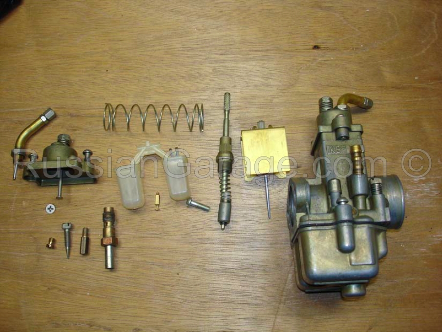
If the steps above are not increasing performance of your Pekars, it’s time to disassemble them for a good cleaning/repair. There are kits out there which have all the wearing components. These kits usually contain jets, gaskets, slide, jet needle, float, float needle, etc. Basically any component which will wear. These kits are easy to install using the following directions.
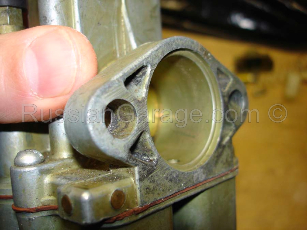
1. Examine the intake face
Here is an example of an intake face which is in need of overhaul.
2. Remove the float bowl
Remove the 2 screws securing the float bowl. Inspect the bowl for contaminants, replace the gasket.
3. Adjust the float level
Hold the unit upside down, the float must be parallel to the carburetor body. Adjust using the float tab.
4. Remove the carburetor cover (37)
Remove the 2 cover screws and examine the throttle spring, slide, needle, etc. If necessary, adjust the needle at this point, if you are not overhauling the carburetor. The needle is adjusted using the plastic locknut.
5. Remove the floats
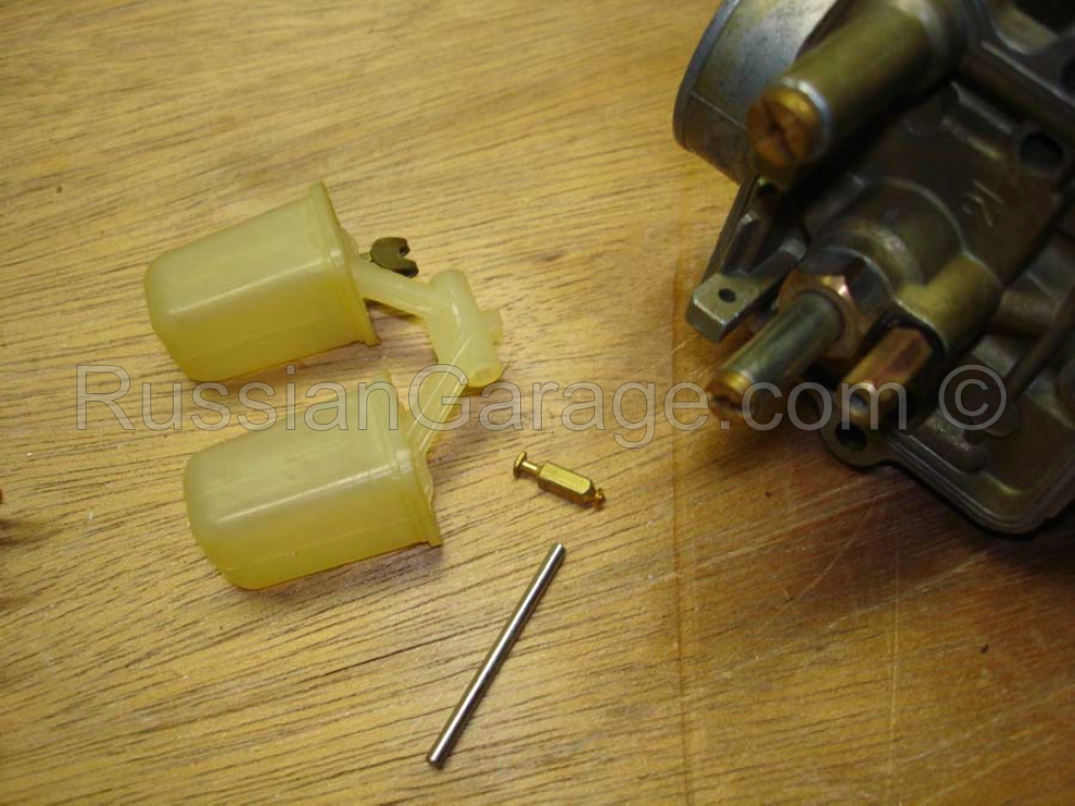
Inspect the float for leaks, check the operation of the float needle. Replace as necessary.
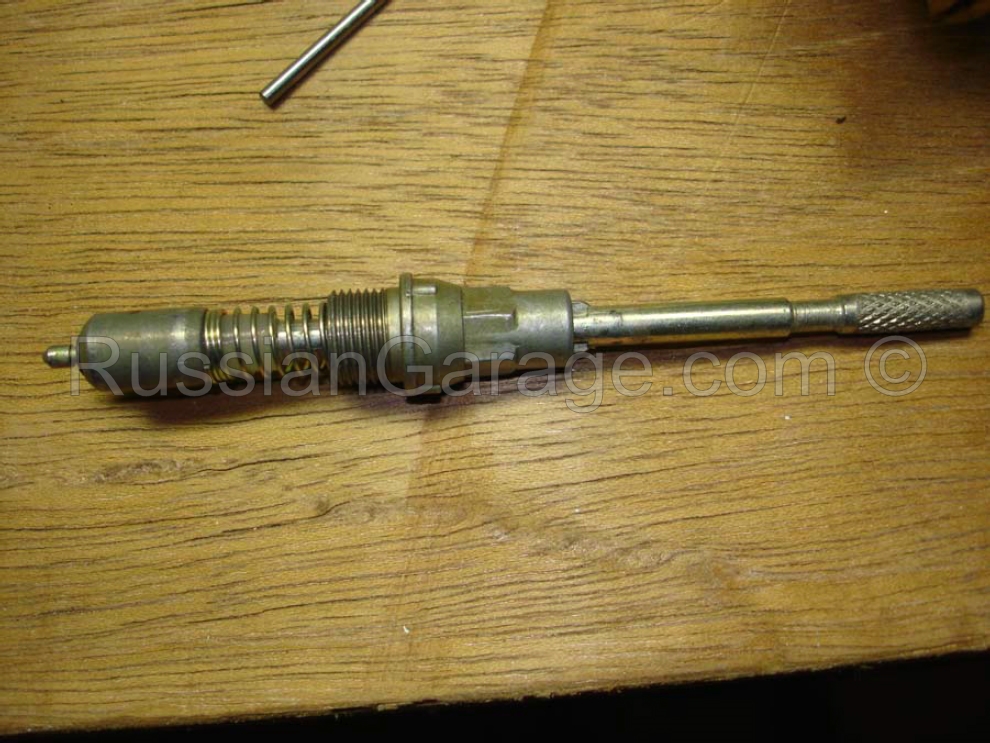
6. Inspect the choke mechanism
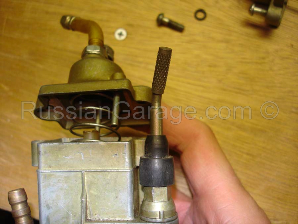
The choke mechanism unscrews from the carburetor body. Inspect/replace the rubber gasket. Here you can see the 90 degree rotation/lock of the choke mechanism.
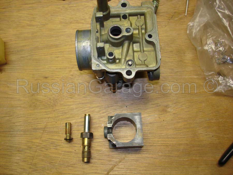
7. Remove the main jet, idle jet, enrichner jet.
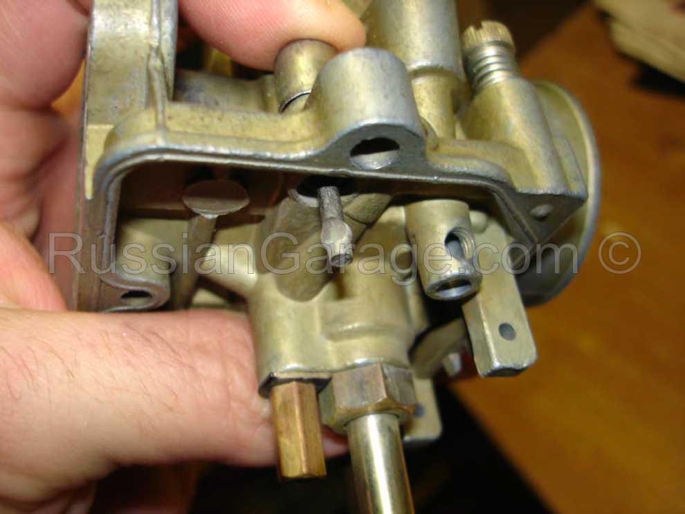
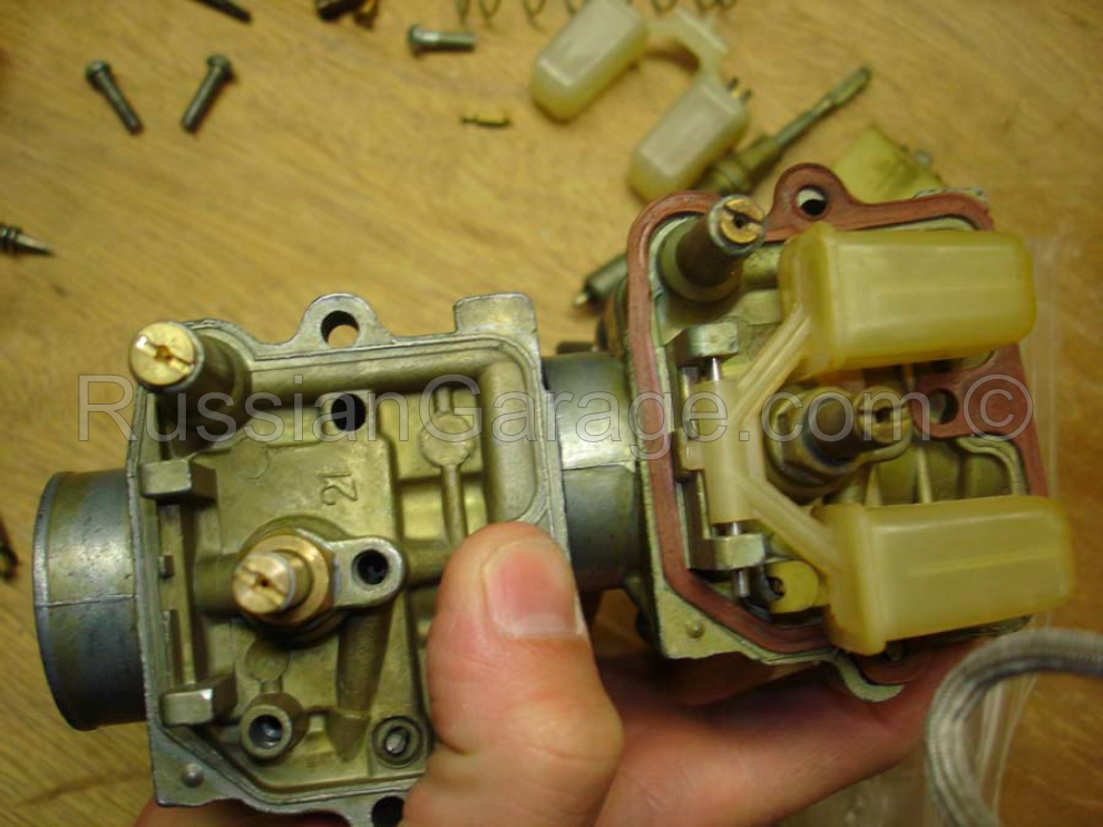
When you remove the main jet, the throttle body will be removed from the atomizer chamber. Note the locknut on the idle jet (left).
8. Tickler check
Check the operation/spring of the tickler circuit (float depressor).
9. Check the idle mixture screw
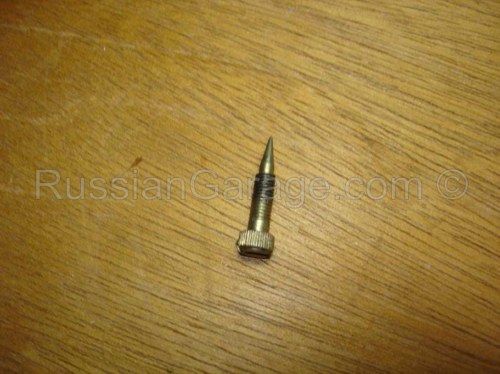
Make sure this screw comes to a nice taper. Replace as necessary. Lack of taper will hinder proper setting of the idle mixture.
10. Clean/Replace all parts.
Now you can see how easy it is to disassemble this carburetor. Reverse the steps to replace/re-install components after cleaning. You can soak the carburetor in gasoline, clean all the jets with compressed air, and reassemble the carburetor for tuning. Make sure all passages are free of contaminants, including the float chamber pressure equalization port (37).
IV. OTHER INFORMATION
Interesting observations on the K65 and some frequently asked questions.
1. K62/65 Comparisons
Here’s a comparison of the 2 carburetors. Very similar, except for the jet sizes.
2. The mysterious throttle limiter
What’s this piece of metal in the top of my K65? My bike is not performing as well as it should. This is the throttle limiter installed at the factory. This was one way to be sure that the engine break-in procedure was followed.
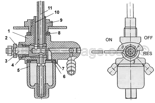
1 – body; 2 – handle; 3- slide valve; 4 – slide valve gasket; 5 – bowl; 6 – filter screen; 7 – filter gasket; 8 – petcock gasket; 9 – threaded bushing; 10 – reserve pipe; 11 – main fuel pipe


